OSPF Protocol
Placement-ready Courses: Enroll Now, Thank us Later!
OSPF is an acronym that stands for Open Shortest Path First. It is a well-known and extensively supported routing protocol. It is an intradomain protocol, which means it is only utilised within a certain region or network. OSPF is an inside gateway protocol created within a single autonomous system.
It is based on a link-state routing algorithm in which each router holds domain information and chooses the shortest path based on this information. Routing’s objective is to learn the routes. OSPF does this by learning about every router and subnet in the whole network. Every router carries the same network information. The router obtains this information via transmitting LSA (Link State Advertisements).
These LSAs include information about every router, subnet, and other networking details. After flooding the LSAs, the OSPF saves the information in a link-state database known as LSDB. The primary purpose is to have the same information about each router in an LSDB.
OSPF Areas:
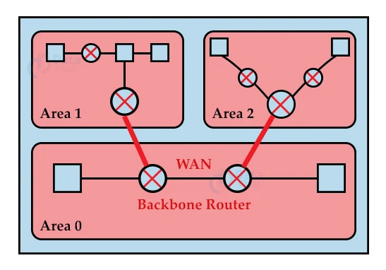
OSPF splits autonomous systems into regions, each of which consists of a collection of networks, hosts, and routers. For ease of management, internet service providers split the internet into autonomous systems, while OSPF further separates the autonomous systems into Areas.
Routers located inside the region broadcast routing information to the whole area.
There is also a specific router in Area. Special routers are those that are present at an area’s boundary, and these special routers are referred to as Area Border Routers. This router aggregates information about one region and distributes it to other areas.
All of the regions inside an autonomous system are linked to the backbone routers, which are part of a major area. A key area’s duty is to facilitate communication between different regions.
Working of OSPF Protocol:
1. The initial stage is to connect with other OSPF neighbours. A neighbour relationship is formed when two connected routers running OSPF on the same connection.
2. The next step is to exchange database data. After becoming neighbours, the two routers communicate LSDB information with one another.
3. The third stage is to decide on the best path. Once the LSDB information has been transmitted, the router selects the optimum route to be added to a routing table based on the SPF calculation.
Forming a Neighbour Relationship:
First, each router chooses a router ID of their own. The router ID is a unique number that identifies each router on a network. The router ID is in the IPv4 address format. There are two methods for setting the router ID. The first is to set the router ID manually, and the second is to let the router decide.
The router determines whether or not the router ID has been manually assigned. It is a router ID if it is manually set. If it is not manually configured, it will select the highest ‘up’ status loopback interface IP address. If no loopback interfaces are available, it will select the highest ‘up’ status non-loopback interface IP address.
An OSPF protocol allows two routers connected via point-to-point or multiple routers connected to communicate with each other. Only when both routers send the HELLO packet to each other do the two routers become adjacent. When both routers receive the acknowledgement of the HELLO packet, they enter a two-way communication mode.
Because OSPF is a link state routing protocol, it allows routers to establish neighbour relationships. The two routers can only be neighbours if they are in the same subnet and have the same area id, subnet mask, timers, and authentication. The OSPF relationship is formed between routers so that they can communicate with one another.
If at least one of the routers is a designated router or backup designated router in a network, or if they are connected via a point-to-point link, the two routers can be neighbours.
Link Types in OSPF:
1. Point-to-point Link:
The point-to-point link connects the two routers directly, with no host or router in between.
2. Transient Link:
A transient link is formed when several routers are connected in a network. The transient link is implemented in two ways:
- Unrealistic topology: An unrealistic topology is one in which all routers are connected to each other.
- Realistic topology: A realistic topology exists when a designated router exists in a network. A router to which all other routers are connected is referred to as a designated router. All packets sent by routers are routed through the designated router.
3. Stub Link:
It’s a network that’s linked to a single router. Data enters the network via a single router and exits the network via the same router.
4. Virtual Link:
If the link between the two routers fails, the administration creates a virtual path between the routers, which could be quite long.
OSPF Message Format:
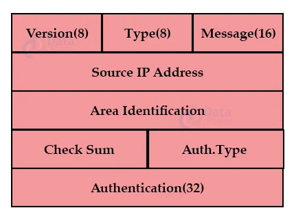
1. Version:
The OSPF protocol version is specified by an 8-bit field.
2. Type:
It is a field of 8 bits. It specifies the OSPF packet type.
3. Message:
It is a 16-bit field that specifies the message’s total length, including the header. As a result, the total length equals the sum of the message and header lengths.
4. Source IP Address:
It specifies the address to which packets are sent. It is a routing IP address for sending data.
5. Area identification:
It defines the area in which the routing occurs.
6. Checksum:
It is used for error detection and correction.
7. Authentication Type:
There are two kinds of authentication: 0 and 1. In this case, 0 indicates that no authentication is available, and 1 indicates that password-based authentication is available.
8. Authentication:
It is a 32-bit field that contains the authentication data’s actual value.
Types of OSPF Packets:
1. Hello:
The Hello packet is used to establish a neighbourhood relationship and determine whether or not the neighbour is reachable. As a result, the Hello packet is used to establish the connection between the routers.
2. Database Description:
If the neighbour router is communicating with the system for the first time after establishing a connection, it sends database information about the network topology to the system so that the system can update or modify accordingly.
3. Link State Request:
The router sends the link-state request to obtain information about a specific route. Assume there are two routers, router 1 and router 2, and router 1 wants to learn more about router 2, so router 1 sends the link state request to router 2. When router 2 receives a link state request, it sends link-state information to router 1.
4. Link State Update:
The router uses the link-state update to advertise the status of its links. The link-state update is used by any router to broadcast the state of its links.
5. Link State Acknowledgement:
By requiring each router to send the acknowledgment on each link state update, link-state acknowledgment improves routing reliability. For example, router A sends the link-state update to routers B and C, and routers B and C respond by sending the link-state acknowledgment to router A, letting the router A know that both routers have received the link-state update.
OSPF States:
1. Down:
The device has not received the HELLO packet if it is in a down state. Down does not mean that the device is physically down; it simply means that the OSPF process has not yet begun.
2. Init:
If the device enters the init state, it means it received the HELLO packet from the other router.
3. 2WAY:
If the device is in a 2WAY state, it means that both routers have received the HELLO packet from the other router, and the connection between the routers is established.
4. Exstart:
When the exchange between the routers begins, both routers enter the Exstart state. The master and slave are chosen based on the router’s id in this state. The sequence of numbers is controlled by the master, who initiates the exchange process.
5. Exchange:
During the exchange state, both routers send a list of LSAs containing a database description to each other.
6. Loading:
The LSR, LSU, and LSA are exchanged during the loading state.
7. Full:
When the LSA exchange is complete, the routers enter the full state.
Router Attributes:
OSPF selects one router as the Designated router and another as the backup designated router before entering the Exstart state. These routers are not the type, but they are router characteristics. In the case of broadcast networks, the router chooses one router to be the primary designated router and another router to be the backup designated router.
The selection of a designated and backup designated router is done to avoid network flooding and to reduce the number of adjacencies. They act as a central point for all routers to exchange routing information. Because point-to-point links are connected directly, DR and BDR are not selected.
If DR and BDR are not selected, the router will send the update to all adjacent neighbours, resulting in network flooding. DR and BDR are elected to avoid this problem. Instead of exchanging updates with other routers in a network segment, each non-DR and non-BDR sends the update only to the DR and BDR.
The BDR acts as a stand-in for the DR while the DR distributes network topology information to other routers in the same area. The BDR also receives routing information from all routers, but it does not distribute it. It only distributes the information if the DR fails.
The non-DR and non-BDR use the multicast address 224.0.0.6 to send routing information to the DR and BDR. The routing information is sent to the multicast address 224.0.0.5 by the DR and BDR.
The rules used in determining DR and BDR are:
- As the DR, the router with the highest OSPF priority is chosen. The highest priority is set to 1 by default.
- If no router has the highest priority, the router with the highest router Id is selected as the DR, and the router with the second-highest priority is selected as the BDR.
Example:
In the above diagram, R1 is designated as the DR, while R2 is designated as the BDR because R1 has the highest router ID and R2 has the second-highest router ID. If the link between R4 and the system fails, R4 notifies only R1 and R4 of the failure. Then, DR notifies all non-DR and non-BDR of the change, and in this case, only R3 is available as a non-DR and non-BDR, with the exception of R4.
Summary:
In this article, we looked at the concept and functioning of the OSPF routing protocol. We also took an in-depth look at the various link types and packets present in the OSPF protocol. The format of the OSPF packet was also covered. Lastly, we looked at the router attributes of the routers used in the functioning of the OSPF protocol.
Did we exceed your expectations?
If Yes, share your valuable feedback on Google