Error Detection And Correction in Computer Network
Placement-ready Online Courses: Your Passport to Excellence - Start Now
An error occurs when the output information does not match the input information. Digital signals suffer from noise during transmission, which can create errors in binary bits travelling from one system to another. That is, a 0 bit may become a 1 bit, or a 1 bit may become a 0.
Many factors, including noise and cross-talk, can contribute to data corruption during transmission. The top layers are unaware of real hardware data processing and work on a generic picture of network architecture. As a result, the top levels anticipate error-free transmission between the systems.
Most programs would not work normally if they received incorrect data. Voice and video applications, for example, may be unaffected and continue to work normally despite occasional problems.
Error Detection:
When a message is sent, it may be jumbled by noise or the data may be damaged. To avoid this, we employ error-detecting codes, which are bits of extra data appended to a digital message to assist us detect whether an error occurred during transmission.
Error Detection Techniques:
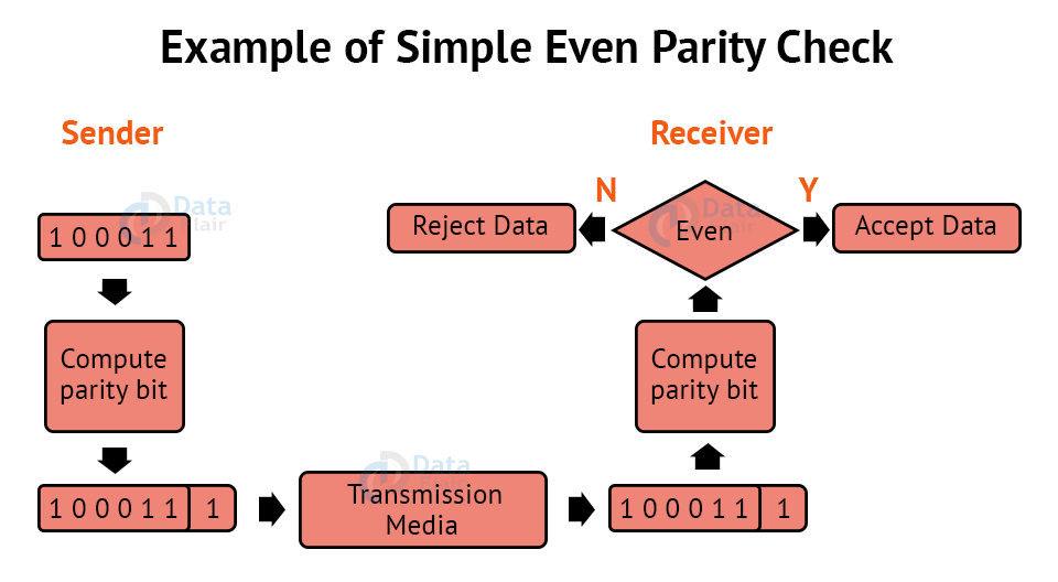
1. Simple Parity Check:
- One extra bit is transmitted in addition to the original bits to make the number of 1s even in the case of even parity or odd in the case of odd parity.
- While creating a frame, the sender counts the amount of 1s in it. If even parity is utilised and the number of 1s is even, one bit with the value 0 is added. In this manner, the number of 1s remains even. If the number of 1s is odd, a value 1 is added to make it even.
- The receiver just counts how many 1s are in a frame. If the number of 1s is even and even parity is utilised, the frame is regarded as uncorrupted and approved. Even if the number of 1s is odd and odd parity is utilised, the frame is not damaged.
- The receiver can identify a single bit flip in transit by counting the number of 1s. However, when more than one bit is incorrect, it is extremely difficult for the receiver to identify the problem.
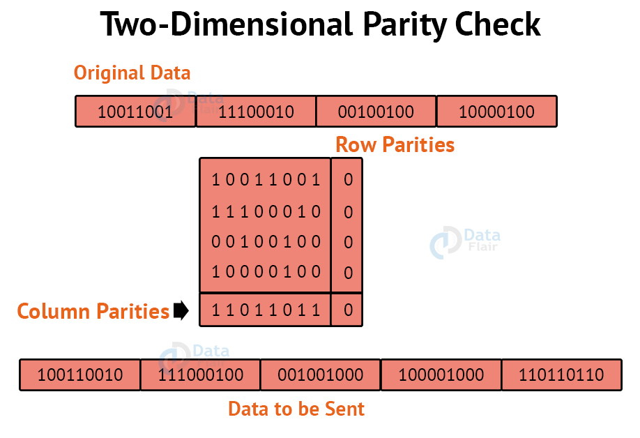
2. Two-Dimensional Parity Check:
For each row, parity check bits are calculated, which is identical to a basic parity check bit. For each column, parity check bits are computed and transmitted together with the data. These are compared with the parity bits calculated on the received data at the receiving end.
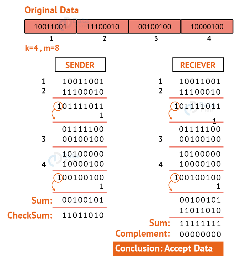
3. Checksum:
The data is split into k segments of m bits each in the checksum error detection technique.
To get the total, the segments are summed at the sender’s end using 1’s complement arithmetic. To obtain the checksum, a complement of the sum is taken.
The checksum segment is sent with the data segments.
To obtain the total, all received segments are summed using 1’s complement arithmetic at the receiver’s end. The sum is then calculated.
If the result is 0, the data is accepted; otherwise, it is rejected.
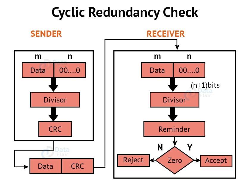
4. Cyclic Redundancy Check:
CRC is an alternative method for determining whether or not a received frame includes valid data. The binary division of the data bits being delivered is used in this approach. Polynomials are used to generate the divisor.
The sender divides the bits that are being transferred and calculates the remainder. The sender inserts the remainder at the end of the original bits before sending the actual bits. A codeword is made up of the actual data bits plus the remainder. The transmitter sends data bits in the form of codewords.
The receiver, on the other hand, divides the codewords using the same CRC divisor. If the remainder consists entirely of zeros, the data bits are validated; otherwise, it is assumed that some data corruption happened during transmission.
Error Correction:
Error Correction codes are used to detect and repair mistakes that occur during data transmission from the transmitter to the receiver.
There are two approaches to error correction:
1. Backward Error Correction:
When a backward mistake is detected, the receiver requests that the sender retransmit the complete data unit.
2. Forward Error Correction:
In this scenario, the error-correcting code is used by the receiver, which automatically corrects the mistakes.
A single extra bit can identify but not repair the mistake.
To correct the mistakes, the specific location of the error must be known. If we wish to compute a single-bit mistake, for example, the error correcting algorithm will identify which one of seven bits is incorrect. We will need to add some more redundant bits to do this.
The number of redundant bits is calculated using the following formula:
2r>=d+r+1
The above formula is used to compute the value of r. For example, if the value of d is 4, the least possible number that fulfils the above relation is 3.
Error Correction Techniques:
1. Hamming Code:
Parity bits: A bit that is added to the original binary data to make sure the total number of 1s is even or odd (in case of even or odd parity respectively).
Even parity: To check for even parity, if the total number of 1s is even, the parity bit value is 0. If the total number of occurrences of 1s is odd, the parity bit value is 1.
Odd Parity: To test for odd parity, if the total number of 1s is even, the parity bit value is 1. If the total number of 1s is odd, the parity bit value is 0.
To produce d+r, an information of ‘d’ bits is added to the redundant bits ‘r’.
Each (d+r) digit’s position is assigned a decimal value.
The ‘r’ bits are assigned to locations 1, 2,….2k-1.
The parity bits are recalculated at the receiving end. The position of an error is determined by the decimal value of the parity bits.
Example: If the data to be transmitted is 1011001
Number of data bits = 7
Thus, number of redundancy bits = 4
Total bits = 7+4 = 11
Redundant bits are always placed at positions that correspond to the power of 2, so the redundant bits will be placed at positions: 1,2,4 and 8.
Redundant bits will be placed here:
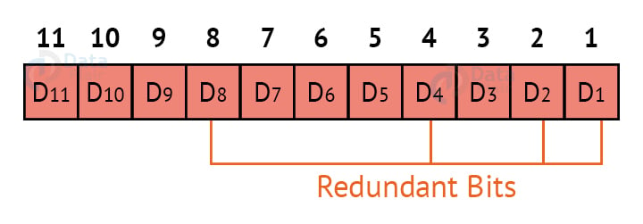
Thus now, all the 11 bits will look like this:
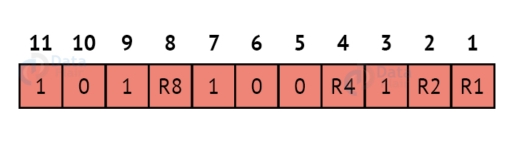
Here, R1, R2, R4 and R8 are the redundant bits.
Determining the parity bits:
R1:
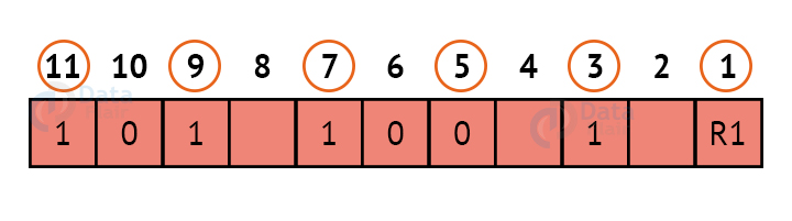
We look at bits 1,3,5,7,9,11 to calculate R1. In this case, because the number of 1s in these bits together is even, we make the R1 bit equal to 0 to maintain even parity.
R2:
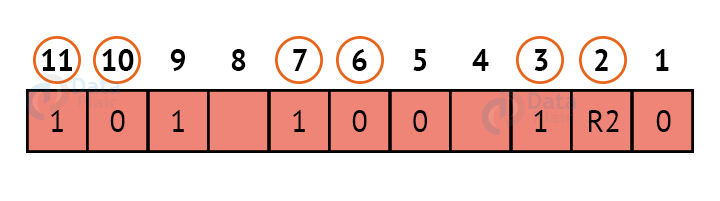
We look at bits 2,3,6,7,10,11 to calculate R2. In this case, because the number of 1s in these bits together is odd, we make the R2 bit equal to 1 to maintain even parity.
R4:
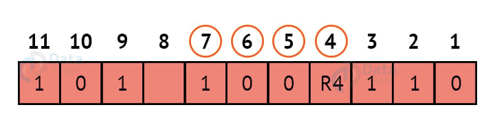
We look at bits 4,5,6,7 to calculate R4. In this case, because the number of 1s in these bits together is odd, we make the R4 bit equal to 1 to maintain even parity.
R8:
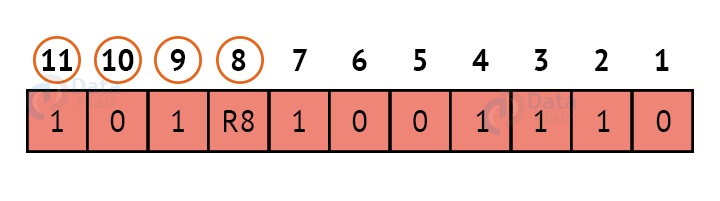
We look at bits 8,9,10,11 to calculate R8. In this case, because the number of 1s in these bits together is even, we make the R8 bit equal to 0 to maintain even parity.
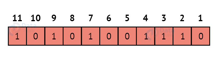
Thus, the final block of data which is transferred looks like this:
Summary:
In this article, we looked at the concepts of error detection and error correction, and the various techniques used in both these concepts. We also looked at the detailed explanation of the Hamming Code method which is the most popular method for error correction, as well as some popular methods for error detection such as Cyclic Redundancy Check, Parity Check etc.
You give me 15 seconds I promise you best tutorials
Please share your happy experience on Google


useful information….Good.