Digital Transmission in Computer Network
Expert-led Online Courses: Elevate Your Skills, Get ready for Future - Enroll Now!
Digital Transmission is a type of signal transmission in which the signals vary discretely with time between two values: one representing the binary number 0 and the other representing 1.
The variable quantity in copper cabling is generally the voltage or electrical potential. Variation in intensity or any other physical quantity is utilised in fiber-optic cabling or wireless communication.
For the transfer of binary information through a communication channel such as a network cable or a telecommunications link, digital signals employ discrete values. A digital signal is transferred one bit at a time on a serial transmission line.
Digital to Digital Conversion/Encoding:
The representation of digital information by a digital signal is known as digital-to-digital encoding.
The process of converting binary 1s and 0s created by a computer into a series of voltage pulses that can be transmitted across a wire is known as digital-to-digital encoding.
This process is also known as Line Coding.
Categories of Digital to Digital Encoding:
1. Unipolar:
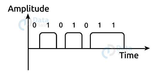
- The voltage pulses are sent via a connection, such as a wire or cable, by a digital transmission system.
- In most encoding schemes, one voltage level represents 0 and another voltage level represents 1.
- Each pulse’s polarity decides whether it is positive or negative.
- Because it only employs one polarity, this form of encoding is known as Unipolar encoding.
- The polarity is allocated to the 1 binary state in Unipolar encoding.
- 1s are represented as positive values, whereas 0s are represented as zero values.
- In Unipolar Encoding, ‘1’ represents a high voltage and ‘0’ represents a zero value.
- Unipolar encoding is less complicated and less expensive to implement.
2. Polar:
To encode binary values, the polar encoding technique utilizes several voltage levels.
There are several types of polar encoding schemes.
a. NRZ (Non-Return to Zero):
- It represents binary values using two distinct voltage levels. In general, positive voltage equals 1 and negative voltage equals 0. It is also NRZ due to the lack of a rest condition.
- The NRZ scheme has 2 types: NRZ-L and NRZ-I.
i. NRZ-L:
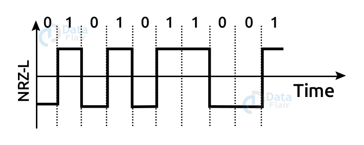
- NRZ-L adjusts the voltage level when a different bit is detected.
ii. NRZ-I:
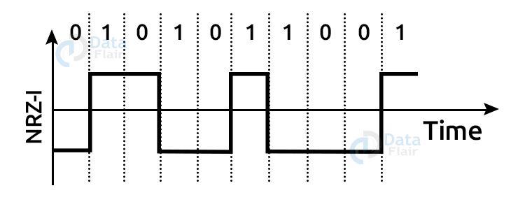
- NRZ-I switches voltage when a 1 is detected.
b. RZ (Return to Zero):
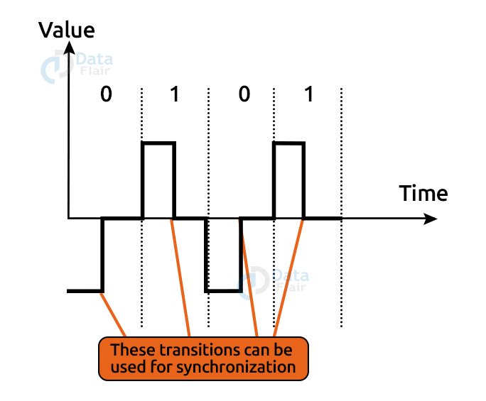
- RZ is an abbreviation for Return to Zero.
- To establish synchronisation, each bit must undergo a signal change. However, in order to have a change with every bit, we must have three values: positive, negative, and zero.
- RZ is a three-value encoding method in which positive voltage represents 1, negative voltage represents 0, and zero voltage indicates none.
- In the RZ system, the signal returns to zero halfway through each period.
- In the RZ scheme, 1 bit is represented by positive-to-zero and 0 bit is represented by negative-to-zero.
c. Biphase:
- Biphase encoding is a type of encoding in which the signal changes in the middle of the bit interval but does not return to zero.
- There are 2 types of biphase encoding schemes:
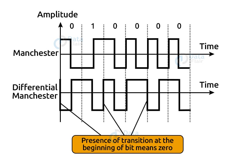
i. Manchester encoding:
- It modifies the signal in the middle of the bit interval without returning to zero for synchronisation.
- A negative-to-positive transition indicates binary 1, and a positive-to-negative transition represents binary 0.
- Manchester encoding has the same degree of synchronisation as the RZ system, but it has two amplitude levels.
ii. Differential Manchester encoding:
- It modifies the signal in the midst of the bit interval for synchronisation, but the bit is determined by the presence or
- absence of the transition at the beginning of the interval. A transition denotes binary 0, whereas no transition denotes binary 1.
- Two signal changes signify 0 in the Differential Manchester Encoding scheme, while one signal change represents 1.
3. Bipolar:
- Positive, negative, and zero voltage levels are represented using the bipolar encoding method.
- The zero voltage level represents the binary value of 0, while the binary 1 is represented by alternating positive and negative voltages in the Bipolar encoding method.
- If the first 1 bit represents positive amplitude, the second 1 bit represents negative voltage, the third 1 bit represents positive amplitude, and so on. Even if the 1 bits are not consecutive, this alternation can occur.
- There are 3 types of schemes under the bipolar encoding scheme:
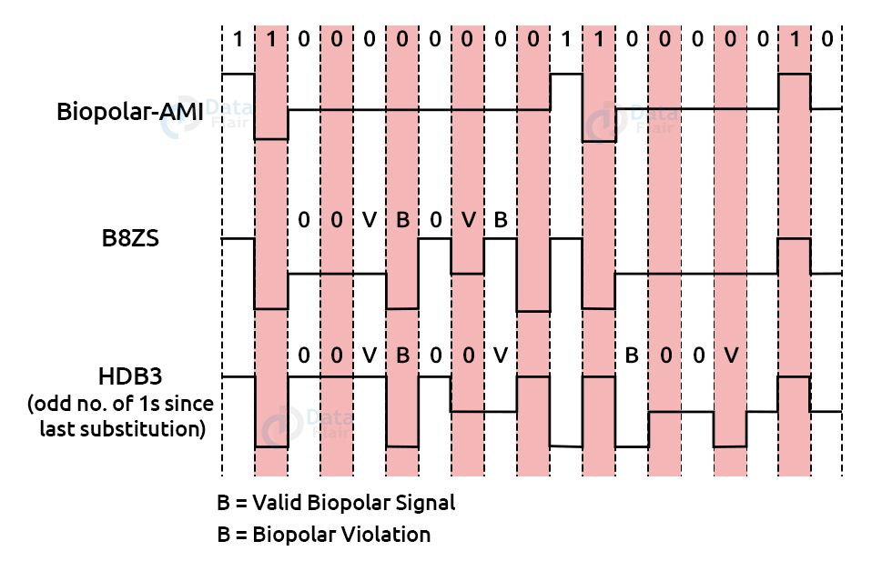
a. AMI (Alternate Mark Inversion):
- AMI is an abbreviation for alternate mark inversion, where the word ‘mark’ is derived from telegraphy and indicates 1. As a result, it can be renamed alternative 1 inversion.
- The 0 bit is represented by zero level in the Bipolar AMI encoding technique, while the 1 bit is represented by alternating positive and negative voltages.
b. B8ZS (Bipolar 8-Zero Substitution):
- This method is used in North America to synchronise a long succession of 0s bits.
- The functioning of B8ZS is identical to that of bipolar AMI in most circumstances, with the exception that it offers synchronisation when a lengthy series of 0s bits occurs.
- B8ZS assures synchronisation of a lengthy string of 0s by forcing artificial signal changes inside the 0 string pattern, known as violations.
- When an eight 0 string occurs, B8ZS makes modifications to the 0s string pattern dependent on the polarity of the preceding 1 bit.
- If the previous 1 bit’s polarity is positive, the eight 0s are then encoded in the following manner: zero, zero, zero, positive, negative, zero, negative, positive.
c. HDB3 (High-Density Bipolar 3):
- The HDB3 method was developed initially in Europe and Japan.
- The HDB3 method is intended to synchronise a lengthy succession of 0s bits.
- The polarity of the preceding bit is used to determine the pattern of violation in the HDB3 method.
- When four 0s occur, HDB3 examines the number of 1s bits that have happened since the last replacement.
- If the number of 1s is odd, the violation occurs on the fourth consecutive 0 bit. If the previous bit’s polarity is positive, the violation is positive. And if the previous bit’s polarity is negative, the violation is negative.
Analog to Digital Conversion:
An analog-to-digital conversion occurs when an analogue signal is converted to digital form.
Assume a human delivers a speech in the form of an analogue signal; we must digitalize the analogue signal to make it less susceptible to noise. It is necessary to reduce the amount of values in an analogue message in order for them to be represented in the digital stream.
The information contained in a continuous waveform is transformed into digital pulses during analog-to-digital conversion.
Categories of Analog to Digital Conversion:
1. PAM (Pulse Amplitude Modulation):
- PAM is an analog-to-digital conversion method.
- The PAM method takes an analogue signal, samples it, and then creates a sequence of digital pulses based on the sampling results. Sampling involves measuring the amplitude of a signal at equal intervals.
- The PAM method is ineffective in data transfer because it converts the original waveform into pulses that are not digital. PAM technique is changed to PCM technique to make them digital.
2. PCM (Pulse Code Modulation):
- The PCM method is used to convert the PAM pulses into a digital signal. PCM quantizes PAM pulses to do this. The technique of assigning integral values in a particular range to sampled instances is known as quantization.
- PAM, quantization, binary encoding, and digital-to-digital encoding are the four operations that make up PCM.
Summary:
In this article, we covered the topic of Digital Transmission in great detail. We looked at the definition of digital to digital conversion, and also the various techniques and methods used in implementing it. We also looked at analog to digital conversion, and the two methods used to achieve good conversion from analog to digital signals.
Did you know we work 24x7 to provide you best tutorials
Please encourage us - write a review on Google


I think, there is something wrong with the differential manchester signal diagram. Please check it.